OpenSCAD is a free software application for creating solid 3D computer-aided design objects. In this tutorial, we will learn how we can create a hexagon in OpenSCAD using different methods. Before going to the implementation part, we assume that you have basic knowledge of how to use OpenSCAD and draw some basic shapes. Here we will go through some of these basic shapes and modify them to create a hexagon in OpenSCAD.
Different Methods to Create a Hexagon in OpenSCAD
First, open OpenSCAD and create a new file. Names the file anything you want. We will use the following methods to create a hexagon in OpenSCAD.
- Hexagon in OpenSCAD using cylinder() method
- Hexagon in OpenSCAD using cube() method
We will use the above methods to create something like this:

Now let us jump into it and create a hexagon.
Hexagon in OpenSCAD Using Cylinder() Method
You might be wondering how we can create a hexagon in OpenSCAD using a cylinder. Well, let us find out. Notice that when you type, cylinder in the OpenSCAD you will be able to see the parameters that it can take.
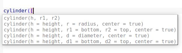
Using these parameters we can adjust the height, radius, and location of the cylinder. But there is one more optional parameter written as $fn which shows the sizes of the fragments. For a hexagon, we have to fix this $fn to 6 because a hexagon has six sides as shown below:
//creating a hexagon using cylinder
cylinder(r=10, h=5, $fn=6);
Output:
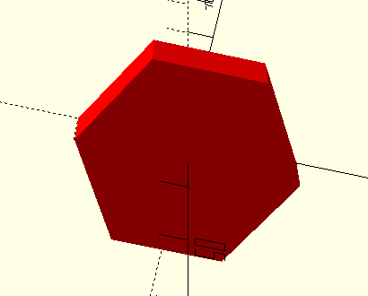
As you can see, we have created a hexagon with a height of 5 and a radius of 10. You can change the color of the hexagon by using the color method as shown below:
//changing the color to red
color("red"){
    //creating a hexagon using cylinder
    cylinder(r=10, h=5, $fn=6);
}
Output:
Hexagon in OpenSCAD Using Cube() Method
Creating a hexagon in OpenSCAD using the cube method requires you to understand some other methods such as rotation and translation as well. Because we will create 6 cubes and just them using translate and rotate methods in such a way that the overall shape will look like a hexagon.
First, let us create a cube:
//creating a cube
cube([10, 10, 5]);
Output:

Now, create another cube but rotate it by 60 degrees. Adjust the translated coordinates as shown below:
//creating a cube
%cube([10, 10, 5]);
//rotating the cube
rotate([0, 0, -60]){

    //Translating the second cube
    translate([-5,-1.36, 0]){
        cube([10, 10, 5]);
    }
}
Output:

In a similar way, we will create other 4 cubes and rotate them and adjust their positions to make them look like a hexagon.
//creating a cube
cube([10, 10, 5]);
//rotating the cube
rotate([0, 0, -60]){

    //Translating the second cube
    translate([-5,-1.36, 0]){
        cube([10, 10, 5]);
    }

    //rotating second cube
    rotate([0, 0, -60]){

    //translating the second cube
        translate([-6.33, -6.35, 0]){
            cube([10, 10, 5]);
    }
}
}
Output:
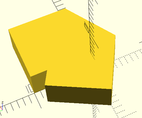
As you can see, half part of the hexagon is done. Now, we will create similar shapes and merge them together to create a hexagon.
//creating a cube
cube([10, 10, 5]);
//rotating the cube
rotate([0, 0, -60]){

    //Translating the second cube
    translate([-5,-1.36, 0]){
        cube([10, 10, 5]);
    }

    //rotating second cube
    rotate([0, 0, -60]){

    //translating the second cube
        translate([-6.33, -6.35, 0]){
            cube([10, 10, 5]);
    }
    //rotating second cube
    rotate([0, 0, -60]){

    //translating the second cube
        translate([-2.7, -10, 0]){
            cube([10, 10, 5]);
    }
     //rotating second cube
    rotate([0, 0, -60]){

    //translating the second cube
        translate([2.4, -8.7, 0]){
            cube([10, 10, 5]);
    }
    //rotating second cube
    rotate([0, 0, -60]){

    //translating the second cube
        translate([3.7, -3.7, 0]){
            cube([10, 10, 5]);
    }
}
}
}
}
}
Output:

As you can see that we have created hexagons in OpenSCAD using the cube method. This hexagon might not be the perfect hexagon as there can be errors in the translation part.
To understand the structure more clearly, we can color each of the cubies with different colors so that it will be easy to see how we have adjusted each of the cubes together to make a hexagon.
//creating a cube
cube([10, 10, 5]);
//rotating the cube
rotate([0, 0, -60]){

    color("red"){
    //Translating the second cube
    translate([-5,-1.36, 0]){
        cube([10, 10, 5]);
    }
}

    //rotating second cube
    rotate([0, 0, -60]){
        color("green"){
    //translating the second cube
        translate([-6.33, -6.35, 0]){
            cube([10, 10, 5]);
        }
    }
    //rotating second cube
    rotate([0, 0, -60]){

        color("black"){
    //translating the second cube
        translate([-2.7, -10, 0]){
            cube([10, 10, 5]);
        }
    }
     //rotating second cube
    rotate([0, 0, -60]){

        color("blue"){
    //translating the second cube
        translate([2.4, -8.7, 0]){
            cube([10, 10, 5]);
        }
    }
    //rotating second cube
    rotate([0, 0, -60]){

        color("pink"){
    //translating the second cube
        translate([3.7, -3.7, 0]){
            cube([10, 10, 5]);
        }
    }
}
}
}
}
}
Output:

Summary
In this short article, we learned how we can create hexagons in OpenSCAD using a couple of methods. We learned to create a hexagon in OpenSCAD using the cylinder and cube method.
Other readings:
How to Implement the Max Filter in Image Processing in Python?
Great content!